Earthworks calculations and design
Areas and volumes
Volumes by construction depth if required
Cut/Fill Lines
Topsoil strip calculations
Plans and cross-sections
Level difference models (isopachytes)
Setting-out
Output to Machine Control Equipment and much more!
LSS is the ideal tool for measuring, designing, monitoring and visualising a wide range of projects within Civil Engineering and Construction.
Most Civil Engineering users are using LSS Vista because they require sections and volumes and, in many cases, benefit from the powerful and unique complex volume calculation options which are in LSS Elite. Especially useful for tendering, the volumes by zones and volumes to construction depth have proved invaluable on many major UK Civils projects.

The £290 million A6 MARR Project, (completion 2018) links the A6 at Hazel Grove to the M56 at Manchester Airport via the existing A555 in Bramhall. We are grateful to John Hicking, "Engineering Manager - Surveying" at Morgan Sindall Construction & Infrastructure for sending us some stunning visualisations of this project. The video (below) begins with a view from inside the project mission room where engineers and managers were shown the plans and flythroughs of the design before working on the project. John says that there is no better way to explain the site than showing everyone a flythrough and LSS 3D Vantage was the software he used (a free 3D Viewer available to LSS Vista and LSS Elite users). You can view the video by hitting the 'Play' button below, or if you cannot see the movie frame, then you can access the video site from this link: https://vimeo.com/223307175/8defe14236

BAM Nuttall Limited is one of the UK's leading civil engineering contractors. John Gaskin, Applications Planning Engineer has been using LSS since 1989 and told us how LSS helps in the day to day monitoring of his most critical sites.
"We use LSS on four types of contract. Firstly, on contaminated land and land reclamation contracts, where the material being moved is expensive. Secondly, for sea defences when armouring is used and precision is required. Thirdly, for road contracts where the earthworks element is significant, and finally for estimating purposes, to help determine a commercially advantageous bid for fixed price contracts."
In describing how he uses LSS, John says. "LSS is a worthwhile, powerful system. An 'Expert' system, easy to use once you know what you are doing." In this respect, he says that it is like AutoCAD, but in many respects is easier to use. John has adopted a 'best of breed' approach to his engineering design and monitoring needs, which means that he uses a number of tools to achieve the results he needs on what are invariably complex jobs. He uses LSS for survey and earthworks monitoring and design and praises the system for its precision and ease of use. With so many different systems in use, John in particular benefits from the data conversion facilities that LSS offers. When asked what he believed to be the single most important benefit of LSS, John said. "The major benefits of LSS are that you always know what is happening on quantities."
Everyone talks about quality of service and guaranteed response. However, at McCarthy Taylor we believe that we give the best possible level of support to our users, but don't take our word for it, just read what John Gaskin thinks. "It's not very often that we have problems, and even less often that there's anything wrong with the software, but when we need help the support is very good." John considers reliability and performance extremely important and is delighted that LSS is strong in both respects.
As if an illustration of the power and flexibility of the software was necessary, the variety of projects on which BAM Nuttall rely on LSS continues to grow. Recently, the British Airways Prospect Park contract involved the excavation and transfer of 2million cubic metres of material, half of which was landfill. The remediation of the site included transfer to parkland, and the preparation of 15 hectares for the new BA Combined Business Centre. In spite of the quantities involved, no materials were imported or exported.
In this case study we look at how David James has been using the the latest software technology to help win earthworks contracts and monitor progress on existing ones. He describes how site-based software needs to be flexible enough to cope with the rigours of the tendering process and robust and reliable enough to adapt when non-standard questions are being asked mid-contract. With several contracts on the go at any one time, he needs technology that is both reliable and fast and relatively quick to learn as one of his jobs is to instruct new engineers in the use of the software.
David is currently with Balfour Beatty and previously with Carillion (previously Alfred McAlpine) and an LSS user since 1994. His main task involves overseeing the earthworks aspects of many large contracts, including the £430m Birmingham Northern Relief Road (M6 Toll).
"I use LSS for the earthworks measures on tenders and live contracts and these have included some large contracts, including the M60 Denton to Medlock job, a 7km long, four lane motorway costing £120m." This was a joint venture with AMEC and the design was undertaken by Mouchel. "We used LSS throughout the tendering and construction phases of the contract and it proved invaluable given the complexity of the site and the amount of material involved. The total cut was 2.3 million³ and fill was 1.2 million³."
Quite a difficult site, the new motorway was to run straight through a reservoir, which necessitated the removal of an existing stone faced earth dam and the design and build of a new one entirely out of reclaimed material. A total of 1.3 million m³ of material was moved in this stage alone. The part of the reservoir that was to be lost was removed and became a borrow pit for the remainder of the site. LSS was used to model the new dam and to calculate the amount of material required in its construction. Of the 800,000m³ of reclaimed material from the old dam, 500,000m³ was used to rebuild it beside the new road.
"The contract involved weekly excavation measures and the design and monitoring of a large borrow pit big enough to hold almost 800,000m³ of material. Weekly surveys were jointly undertaken by the contractors and the RE, but everyone else had trouble keeping up with our weekly calculations until, that is, they started to use LSS."
"As material was excavated it was classified according to its grade and suitability for re-use (each sample having a unique 3D reference). The surface coding capabilities of LSS allowed us to keep track of these different materials and to produce a single volume report at the end of each week that told us how each material had changed in size. Even though this wasn't a design and build contract, the fact that both parties had LSS enabled us to agree monthly figures with the Quantity Surveyors, so when at the end of the contract we did a final measure, there was no argument over the final quantities."
LSS was used, primarily in four tasks.
1 Volume and design checks at the tendering stage
2 Earthworks outline design
3 Weekly cut and fill volumes to assist in programme planning and valuation
4 Motorway structures modelled and setting-out information produced.
David has worked on other major contracts including a runway and taxiway reconstruction at RAF Fairford. This was a £50 million Design & Build job in joint venture with SIAC, from designs by Burks Green. It involved breaking out approximately 215,000 m³ of existing blacktop and concrete and replacing it with almost 290,000m³ of mostly Pavement Quality Concrete. LSS was used for recording daily 'as-built' levels and monitoring breakout quantities
"We were provided with just the design outline and strings where the slope grades change. What we did was drape the 2D bay-layout design outline onto the 3D string model within LSS in order to provide the necessary information for the 3 paving machines employed on the site. While much of the job has been built to the original design levels, there are two zones where we had some flexibility, depending on the amount of material we had available to us following the recycling of breakout material. Having LSS on-site allowed us to raise or lower surfaces very easily to increase or decrease the amount of fill required. By zoning the site in this way we were able to produce one volume report which included all elements of the site."
David's other major project was the 43km long M6 Toll where he used the techniques learned on previous jobs to great effect on this challenging earthworks balancing exercise.

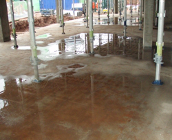
I've worked on a lot of construction projects which have involved the laying of concrete slab floors and frequently encounter situations such as the one shown in this photograph.
Ideally you’d have a smooth surface without any depressions. After a spot or two of rain you can see the depressions in this concrete floor, but quantifying this unevenness can be a time consuming job. Traditionally, this has been called a 'puddleometer' for obvious reasons.

The “National Structural Concrete Specification for Building Construction, 3rd Ed. 2004” (NSCS) sets out the precise parameters within which everyone in the construction industry works.
In NSCS Part 1 there are three specific measures, two for the overall level of the concrete floor and one which specifies the waviness of the surface. Let's look at each in turn.
1) Permissible deviation from intended level shall be ±10mm. This means that nowhere on the floor should be more than 10mm higher or lower than the designed level. But, further…
2) Deviation in level between two points 6m apart shall be less than 15mm
3) Deviation at any point under a 3m straight edge placed at any position on the floor shall be less than 10mm

Determining whether a floor is level is quite straightforward, but when it comes to measuring the waviness of the surface, relying on someone laying a 3m straight edge at exactly the right place is difficult and ultimately not traceable. So, what we did was approach McCarthy Taylor to see if there was anything they could do with LSS to help us work out these measurements. After a development meeting with McCarthy Taylor it wasn't long before we had a working solution to our problem in the form of 'Output / Floor Assessment'.
This is how we do it now. Using a Leica EDM with reflectorless measuring capability we take a roughly 1 metre grid of points straight onto the dry (and clean) concrete surface. At the same time we also pick up other as-built information such as the position of columns, walls, slab edges, drainage and recesses. The floor information is then filtered into an LSS model, surface coded and the Floor Assessment run.
We are then able to run three analyses. 1) The deviation of the floor from the design level 2) The level deviation over any stipulated distance of usually 6 metres and 3) the deviation relative to a straight edge of usually 3 metres.
So, for every grid position LSS effectively draws a line through the model and then repeats the exercise, this time rotated by a user-defined interval until it has completed a full 360 degrees. If we want to know the deviation from design of suspended floor thickness we run a separate analysis which compares surveys of the top and bottom of the same slab, stored as separate surveys in LSS.
The results show clearly where the design tolerances have and have not been met. In fact, on an individual project the specification may call for even tighter tolerances, such as when the finished floor needs to be smoother, such as in plant rooms or where heavy machinery is being wheeled around. What the contractor wants to avoid is having to grind down whole areas of the floor because it is too high. For instance, if a floor is 15mm too high across its entire surface, but we have sufficient headroom to accommodate it, we may decide to alter the design as long as it doesn't impact on other aspects of the build.
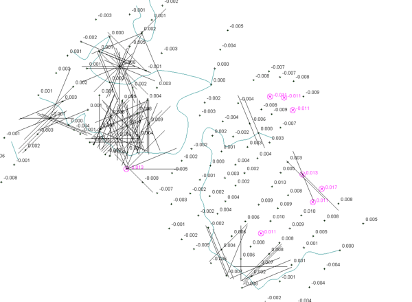
What we see here isn't the consequence of a bizarre game of 'Pick-up-sticks', it's the result of the 3m straight edge calculation. The lines represent where the stipulated deviation has been exceeded and requires some attention.

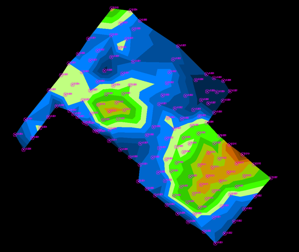
Below we see the result of a level analysis. The coloured heightbands represent the difference between design and built levels for the floor. In this example, blues represent 'below design', browns represent 'above design' and greens are within tolerance of design.

What the Floor Assessment command does is allow us to quantify the floor characteristics and compare them to the design and project specifications. Critically, it allows us to do this using standard survey equipment which we already have on-site. The quality of the results and the cost savings make this a win-win for us and our clients.
The Floor Assessment command is available in LSS Elite.